display显示
约 612 个字 356 行代码 9 张图片 预计阅读时间 6 分钟
背景颜色
from OCC.Display.SimpleGui import init_display
from OCC.Core.BRepPrimAPI import BRepPrimAPI_MakeBox
from OCC.Core.Quantity import (
Quantity_Color,
Quantity_NOC_ALICEBLUE,
Quantity_NOC_ANTIQUEWHITE,
)
display, start_display, add_menu, add_function_to_menu = init_display()
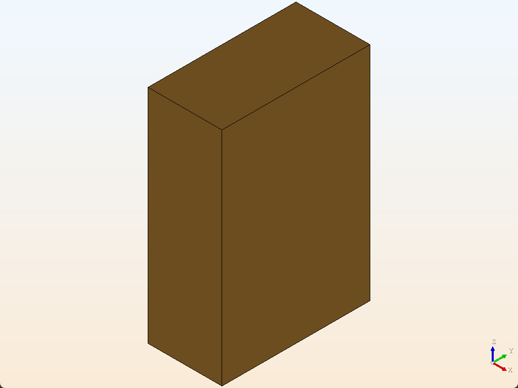
my_box = BRepPrimAPI_MakeBox(10.0, 20.0, 30.0).Shape()
# 设置显示窗口的背景为 渐变色
display.View.SetBgGradientColors(
Quantity_Color(Quantity_NOC_ALICEBLUE),
Quantity_Color(Quantity_NOC_ANTIQUEWHITE),
2, # 渐变类型: 垂直
True, # 是否立即更新视图
)
display.Repaint() # 确保背景颜色更新
display.DisplayShape(my_box, update=True)
start_display()
callback
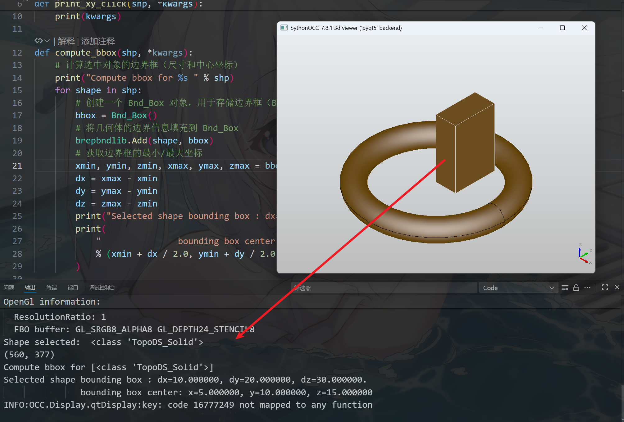
用户可以添加鼠标回调事件,官网的案例中,当点击几何体时会打印一些几何体的信息:
from OCC.Core.BRepPrimAPI import BRepPrimAPI_MakeBox, BRepPrimAPI_MakeTorus
from OCC.Core.Bnd import Bnd_Box
from OCC.Core.BRepBndLib import brepbndlib
from OCC.Display.SimpleGui import init_display

def print_xy_click(shp, *kwargs):
    # 当用户点击 3D 对象时,打印选中对象的 Python 对象信息
    for shape in shp:
        print("Shape selected: ", shape)
    print(kwargs)

def compute_bbox(shp, *kwargs):
    # 计算选中对象的边界框(尺寸和中心坐标)
    print("Compute bbox for %s " % shp)
    for shape in shp:
        # 创建一个 Bnd_Box 对象,用于存储边界框(Bounding Box)数据的类
        bbox = Bnd_Box()
        # 将几何体的边界信息填充到 Bnd_Box
        brepbndlib.Add(shape, bbox)
        # 获取边界框的最小/最大坐标
        xmin, ymin, zmin, xmax, ymax, zmax = bbox.Get()
        dx = xmax - xmin
        dy = ymax - ymin
        dz = zmax - zmin
        print("Selected shape bounding box : dx=%f, dy=%f, dz=%f." % (dx, dy, dz))
        print(
            "               bounding box center: x=%f, y=%f, z=%f"
            % (xmin + dx / 2.0, ymin + dy / 2.0, zmin + dz / 2.0)
        )

display, start_display, add_menu, add_function_to_menu = init_display()

# 将两个函数绑定到鼠标选择事件
display.register_select_callback(print_xy_click)
display.register_select_callback(compute_bbox)

# 创建几何体
my_box = BRepPrimAPI_MakeBox(10.0, 20.0, 30.0).Shape()
my_torus = BRepPrimAPI_MakeTorus(30.0, 5.0).Shape()

display.DisplayShape(my_torus)
display.DisplayShape(my_box, update=True)

start_display()
AddClipPlane
from OCC.Display.SimpleGui import init_display
from OCC.Core.BRepPrimAPI import BRepPrimAPI_MakeBox
from OCC.Core.Graphic3d import Graphic3d_ClipPlane
from OCC.Core.Quantity import Quantity_Color, Quantity_TOC_RGB
from OCC.Core.gp import gp_Pln, gp_Pnt, gp_Dir
from OCC.Core.Bnd import Bnd_Box
from OCC.Core.BRepBndLib import brepbndlib


def shape_center(shape):
    """返回形状包围盒中心点 (cx, cy, cz)。"""
    bbox = Bnd_Box()
    brepbndlib.Add(shape, bbox)
    xmin, ymin, zmin, xmax, ymax, zmax = bbox.Get()
    return (0.5 * (xmin + xmax), 0.5 * (ymin + ymax), 0.5 * (zmin + zmax))


def make_clip_plane(point, normal, rgb=(0.75, 0.78, 0.85)):
    """
    创建一个启用 capping 的裁切平面:
    - point: 平面上一点 (x, y, z)
    - normal: 法向量 (nx, ny, nz)
    - rgb: 截面填充颜色 (0~1)
    """
    clip = Graphic3d_ClipPlane()
    clip.SetOn(True)            # 启用
    clip.SetCapping(True)       # 开启截面填充
    clip.SetCappingHatch(True)  # 带阴影线

    mat = clip.CappingMaterial()
    col = Quantity_Color(*rgb, Quantity_TOC_RGB)
    mat.SetAmbientColor(col)
    mat.SetDiffuseColor(col)
    clip.SetCappingMaterial(mat)

    pln = gp_Pln(gp_Pnt(*point), gp_Dir(*normal))
    clip.SetEquation(pln)
    return clip


def main():
    display, start_display, *_ = init_display()

    my_box = BRepPrimAPI_MakeBox(10.0, 20.0, 30.0).Shape()
    ais = display.DisplayShape(my_box, update=True)[0]

    # 计算中心点
    cx, cy, cz = shape_center(my_box)

    # 三个正交裁切平面(均过中心)
    plane_x = make_clip_plane((cx, cy, cz), (1, 0, 0), rgb=(0.80, 0.70, 0.70))  # X 向
    plane_y = make_clip_plane((cx, cy, cz), (0, 1, 0), rgb=(0.70, 0.80, 0.70))  # Y 向
    plane_z = make_clip_plane((cx, cy, cz), (0, 0, 1), rgb=(0.70, 0.75, 0.90))  # Z 向

    # 添加到可交互对象
    ais.AddClipPlane(plane_x)
    ais.AddClipPlane(plane_y)
    ais.AddClipPlane(plane_z)

    # 可视化
    display.FitAll()
    start_display()

if __name__ == "__main__":
    main()
- 想保留另一半(翻面裁切)的话,可以把对应法向量取反,比如
(1, 0, 0) → (-1, 0, 0) - 想把裁切位置从中心改为任意截面(例如
x = 6):把point改成(6, cy, cz)且法向仍为(1, 0, 0)
AIS_Shape
from OCC.Core.AIS import AIS_Shape
from OCC.Core.BRepPrimAPI import BRepPrimAPI_MakeBox
from OCC.Display.SimpleGui import init_display
from OCC.Core.Quantity import (
Quantity_Color, Quantity_TOC_RGB,
Quantity_NOC_BLUE1
)
display, start_display, add_menu, add_function_to_menu = init_display()
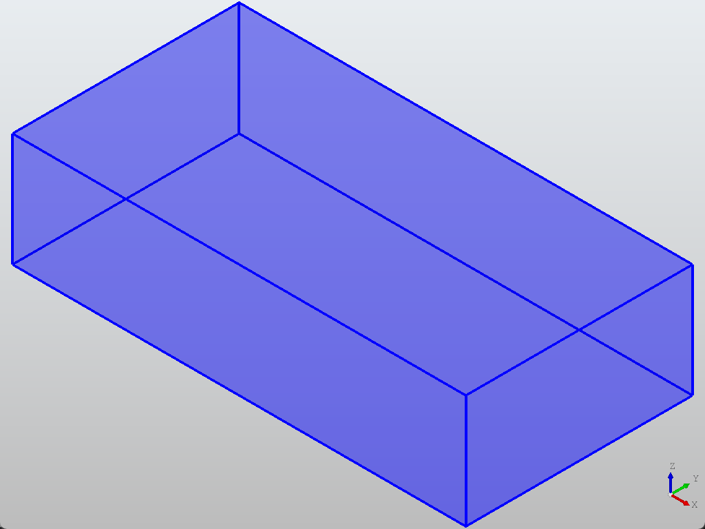
s = BRepPrimAPI_MakeBox(200, 100, 50).Shape()
ais_shp = AIS_Shape(s)
ais_shp.SetWidth(4) # 设置线宽
ais_shp.SetTransparency(0.50) # 设置透明度
ais_shp.SetColor(Quantity_Color(Quantity_NOC_BLUE1)) # 设置颜色
# Get Context
ais_context = display.GetContext()
ais_context.SetAutoActivateSelection(False) # 鼠标选中时不影响线颜色的变化
ais_context.Display(ais_shp, True)
display.View_Iso()
display.FitAll()
start_display()
通过AIS_Shape(s),可以获得该形状的特征。后处理显示时更加灵活。上面代码可创建一个透明度为10%,边缘线宽为4的box:
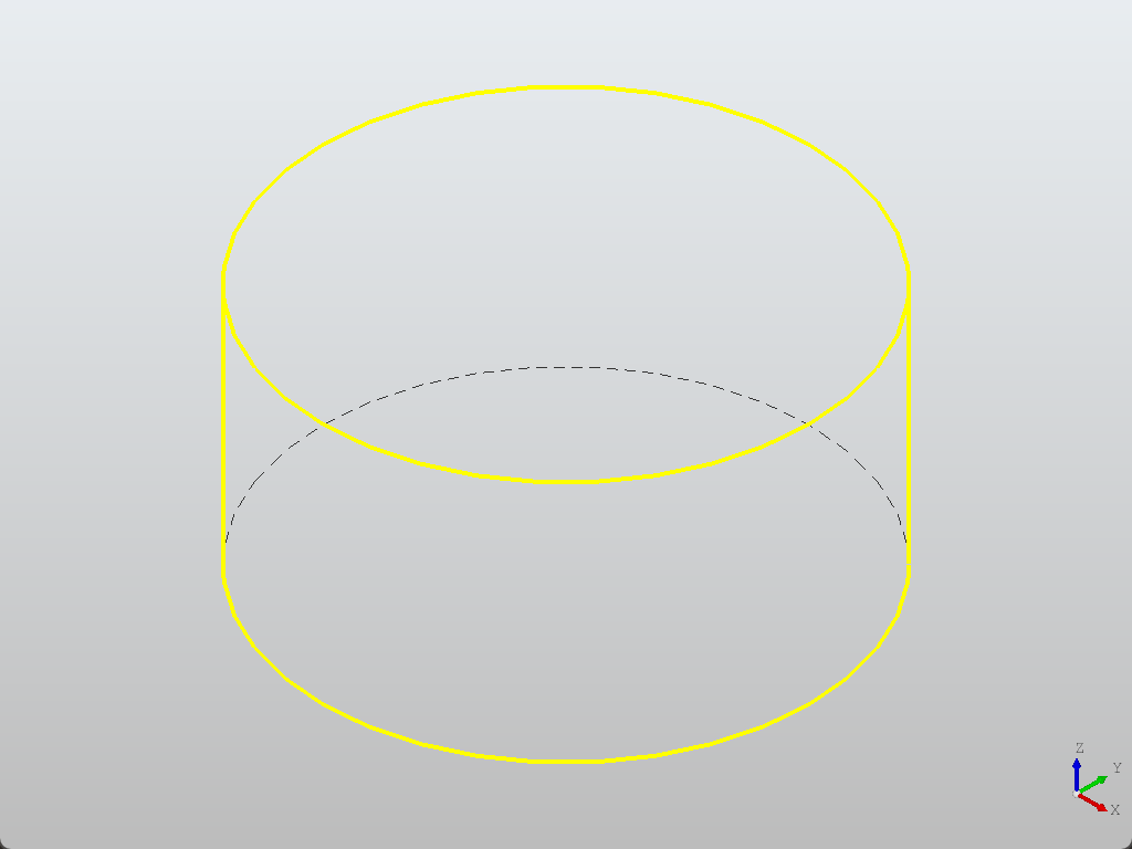
HLR 模式
SetModeHLR():设置为 HLR 模式(Hidden Line Removal,隐藏线消除模式),在这个模式下,物体只显示轮廓线和可见边。
from OCC.Core.BRepPrimAPI import BRepPrimAPI_MakeCylinder
from OCC.Display.SimpleGui import init_display

display, start_display, add_menu, add_function_to_menu = init_display()

# HLR模式
display.SetModeHLR()

# 管理交互式对象
ais_context = display.GetContext()

# 控制绘制参数
drawer = ais_context.DefaultDrawer()
drawer.SetIsoOnPlane(True) # 启用等参线(在曲面上画的辅助线)

la = drawer.LineAspect()
la.SetWidth(4)

line_aspect = drawer.SeenLineAspect()   # 获取可见线样式
drawer.EnableDrawHiddenLine()           # 启用隐藏线显示
line_aspect.SetWidth(4)

# 把这个线样式应用到线框显示模式
drawer.SetWireAspect(line_aspect)

s = BRepPrimAPI_MakeCylinder(50.0, 50.0).Shape()
display.DisplayShape(s)

display.View_Iso()
display.FitAll()
start_display()
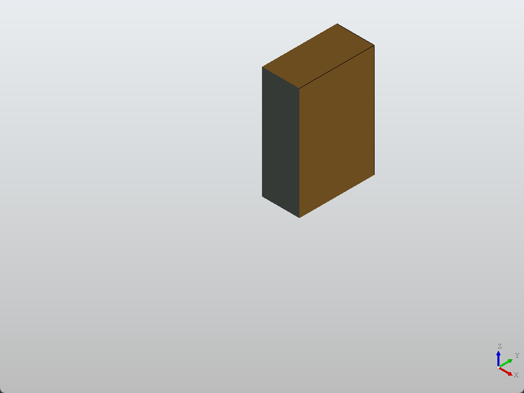
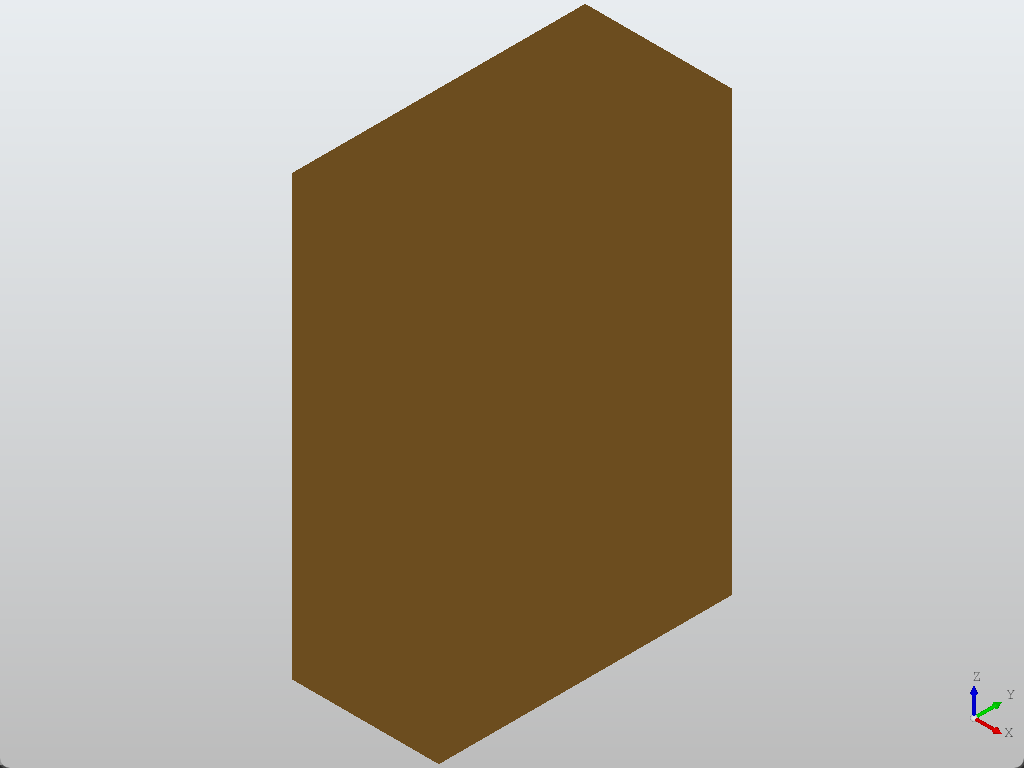
隐藏边界线
SetFaceBoundaryDraw(False):不绘制面边界线
from OCC.Display.SimpleGui import init_display
from OCC.Core.BRepPrimAPI import BRepPrimAPI_MakeBox

display, start_display, add_menu, add_function_to_menu = init_display()
my_box = BRepPrimAPI_MakeBox(10.0, 20.0, 30.0).Shape()

display.default_drawer.SetFaceBoundaryDraw(False)
display.DisplayShape(my_box, update=True)
start_display()
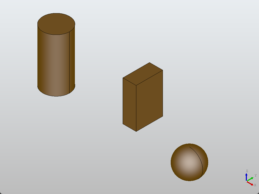
隐藏/删除/重新显示
from OCC.Core.BRepPrimAPI import (
    BRepPrimAPI_MakeBox,
    BRepPrimAPI_MakeCylinder,
    BRepPrimAPI_MakeSphere,
)
from OCC.Core.BRepBuilderAPI import BRepBuilderAPI_Transform
from OCC.Core.gp import gp_Trsf, gp_Vec
from OCC.Display.SimpleGui import init_display

display, start_display, add_menu, add_function_to_menu = init_display()

a_box = BRepPrimAPI_MakeBox(10.0, 20.0, 30.0).Shape()

tr1 = gp_Trsf(); tr1.SetTranslation(gp_Vec(50, 0, 0))
a_sphere = BRepBuilderAPI_Transform(BRepPrimAPI_MakeSphere(10.0).Shape(), tr1, False).Shape()

tr2 = gp_Trsf(); tr2.SetTranslation(gp_Vec(-50, 0, 0))
a_cylinder = BRepBuilderAPI_Transform(BRepPrimAPI_MakeCylinder(10.0, 40.0).Shape(), tr2, False).Shape()

ais_box = display.DisplayShape(a_box)[0]
ais_sphere = display.DisplayShape(a_sphere)[0]
ais_cylinder = display.DisplayShape(a_cylinder)[0]

display.FitAll()

# 隐藏(从视图中擦除,但仍在上下文里,可再次显示)
# display.Context.Erase(ais_box, True)
# display.Context.Erase(ais_sphere, True)
# display.Context.Erase(ais_cylinder, True)

# 重新显示
# display.Context.Display(ais_box, True)
# display.Context.Display(ais_sphere, True)
# display.Context.Display(ais_cylinder, True)

# 永久移除
# display.Context.Remove(ais_box, True)
# display.Context.Remove(ais_sphere, True)
# display.Context.Remove(ais_cylinder, True)

# 全部隐藏/清除
# display.EraseAll()                         # 视图层面的全部擦除
# display.Context.EraseAll(True)             # 上下文层面的全部擦除
# display.Context.RemoveAll(True)            # 上下文层面的全部移除

# 进入交互
start_display()
display.DisplayShape(a_box)这里返回的是列表,如果是display.DisplayShape(a_box)[0]则返回的是AIS_Shape对象,可进行下一步的操作,当然也可以将Shape列表传入display.DisplayShape然后进行索引
视图层面
- 只和 当前窗口里的绘图缓冲区 打交道
- 比如
display.EraseAll():清空屏幕,把所有图形从画布上移除 - 但是对象本身依旧保存在 AIS_InteractiveContext(上下文)里,下次
FitAll()或者Redisplay()又能让它们重新出现
上下文层面
- 管理的是 AIS 对象本身的生命周期和显示状态
- 这里有三种常用操作:
Erase(ais_shape, True)- 隐藏对象(从上下文里标记为不显示),但还在上下文里保存着,可以再
Display()
- 隐藏对象(从上下文里标记为不显示),但还在上下文里保存着,可以再
Remove(ais_shape, True)- 彻底移除上下文,不再管理这个对象。以后要看必须重新
DisplayShape()创建新的 AIS
- 彻底移除上下文,不再管理这个对象。以后要看必须重新
EraseAll()/RemoveAll()- 同理,只是对所有对象操作
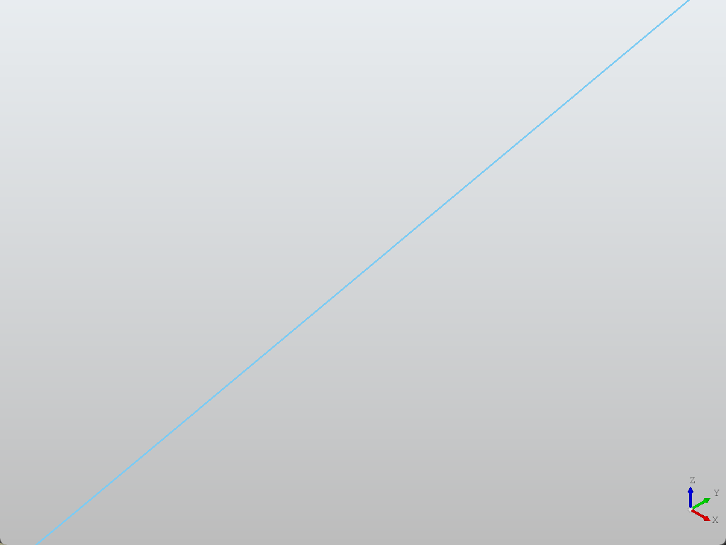
线段样式
from OCC.Display.SimpleGui import init_display
from OCC.Core.gp import gp_Pnt, gp_Dir
from OCC.Core.Geom import Geom_Line
from OCC.Core.AIS import AIS_Line
from OCC.Core.Prs3d import Prs3d_Drawer, Prs3d_LineAspect
from OCC.Core.Quantity import Quantity_Color, Quantity_TOC_RGB, Quantity_NOC_RED
from OCC.Core.Aspect import (
    Aspect_TOL_SOLID,
    Aspect_TOL_DASH,
    Aspect_TOL_DOT,
    Aspect_TOL_DOTDASH,
)

display, start_display, add_menu, add_function_to_menu = init_display()

p = gp_Pnt(2.0, 3.0, 4.0)
d = gp_Dir(4.0, 5.0, 6.0)
gline = Geom_Line(p, d)

ais_line = AIS_Line(gline)

# 通过 Drawer + LineAspect 设置样式
drawer = Prs3d_Drawer()

color = Quantity_Color(0.2, 0.6, 0.9, Quantity_TOC_RGB)

# 线型:可选 Aspect_TOL_SOLID / _DASH / _DOT / _DOTDASH
line_type = Aspect_TOL_SOLID

# 线宽
width = 3.0

# 组合成线样式对象
aspect = Prs3d_LineAspect(color, line_type, width)
drawer.SetLineAspect(aspect)
ais_line.SetAttributes(drawer)

display.Context.Display(ais_line, True)
display.FitAll()
start_display()
有关线型的样式,参考OCC文档:
Aspect_TOL_SOLID |
continuous |
|---|---|
Aspect_TOL_DASH |
dashed 2.0,1.0 (MM) |
Aspect_TOL_DOT |
dotted 0.2,0.5 (MM) |
Aspect_TOL_DOTDASH |
mixed 10.0,1.0,2.0,1.0 (MM) |
Aspect_TOL_USERDEFINED |
defined by Users |
点的样式
import sys
from OCC.Core.gp import gp_Pnt
from OCC.Core.Geom import Geom_CartesianPoint
from OCC.Core.Quantity import Quantity_Color, Quantity_TOC_RGB
from OCC.Core.Aspect import (
Aspect_TOM_POINT,
Aspect_TOM_PLUS,
Aspect_TOM_STAR,
Aspect_TOM_X,
Aspect_TOM_O,
Aspect_TOM_O_POINT,
Aspect_TOM_O_PLUS,
Aspect_TOM_O_STAR,
Aspect_TOM_O_X,
Aspect_TOM_RING1,
Aspect_TOM_RING2,
Aspect_TOM_RING3,
Aspect_TOM_BALL,
)
from OCC.Core.AIS import AIS_Point
from OCC.Core.Prs3d import Prs3d_PointAspect, Prs3d_Drawer
from OCC.Display.SimpleGui import init_display
display, start_display, add_menu, add_function_to_menu = init_display()
ALL_ASPECTS = [
Aspect_TOM_POINT, # 实心点
Aspect_TOM_PLUS, # 加号
Aspect_TOM_STAR, # 星号
Aspect_TOM_X, # X形
Aspect_TOM_O, # 空心圆
Aspect_TOM_O_POINT, # 带点的圆
Aspect_TOM_O_PLUS, # 带加号的圆
Aspect_TOM_O_STAR, # 带星号的圆
Aspect_TOM_O_X, # 带X的圆
Aspect_TOM_RING1, # 单环
Aspect_TOM_RING2, # 双环
Aspect_TOM_RING3, # 三环
Aspect_TOM_BALL, # 球体
]
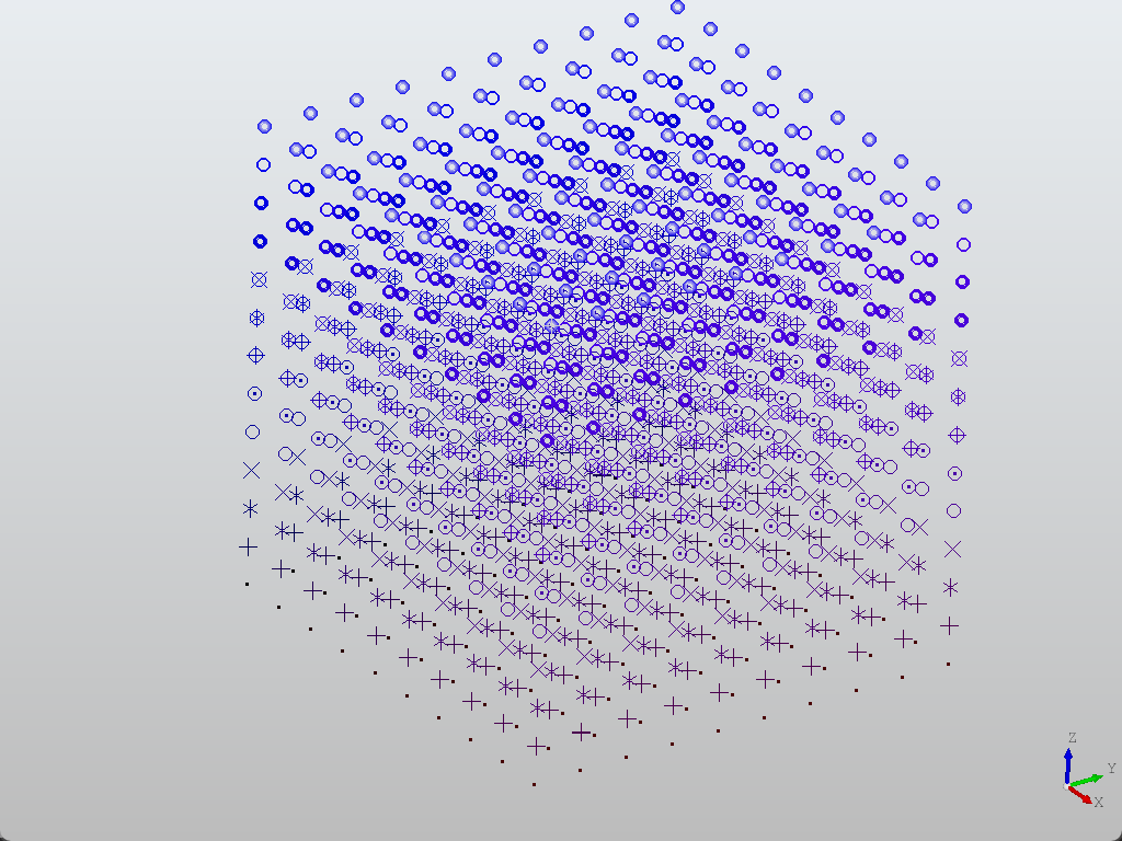
def pnt():
# 创建10x10的点阵,每个Z层使用不同的标记类型
for idx in range(10):
for idy in range(10):
for idz, aspect in enumerate(ALL_ASPECTS):
x = 0 + idx * 0.1
y = 0 + idy * 0.1
z = 0 + idz / len(ALL_ASPECTS)
p = Geom_CartesianPoint(gp_Pnt(x, y, z))
color = Quantity_Color(x / len(ALL_ASPECTS), 0, z, Quantity_TOC_RGB)
# 创建交互式点对象
ais_point = AIS_Point(p)
# 获取当前绘图器
drawer = ais_point.Attributes()
# 创建点显示属性:标记类型、颜色、大小(3.0)
asp = Prs3d_PointAspect(aspect, color, 3)
# 设置点属性并应用到对象
drawer.SetPointAspect(asp)
ais_point.SetAttributes(drawer)
display.Context.Display(ais_point, False)
display.FitAll()
start_display()
def exit(event=None):
sys.exit()
if __name__ == "__main__":
pnt()
有关点的样式,参考OCC文档:
| Aspect_TOM_POINT | point . |
|---|---|
Aspect_TOM_PLUS |
plus + |
Aspect_TOM_STAR |
star * |
Aspect_TOM_X |
cross x |
Aspect_TOM_O |
circle O |
Aspect_TOM_O_POINT |
a point in a circle |
Aspect_TOM_O_PLUS |
a plus in a circle |
Aspect_TOM_O_STAR |
a star in a circle |
Aspect_TOM_O_X |
a cross in a circle |
Aspect_TOM_RING1 |
a large ring |
Aspect_TOM_RING2 |
a medium ring |
Aspect_TOM_RING3 |
a small ring |
Aspect_TOM_BALL |
a ball with 1 color and different saturations |
Aspect_TOM_USERDEFINED |
defined by Users (custom image) |