二维模型创建
约 373 个字 219 行代码 6 张图片 预计阅读时间 4 分钟
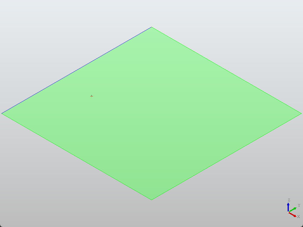
点、线、面
from OCC.Core.gp import gp_Pnt
from OCC.Core.BRepBuilderAPI import (BRepBuilderAPI_MakeVertex,
                                    BRepBuilderAPI_MakeEdge,
                                    BRepBuilderAPI_MakeWire,
                                    BRepBuilderAPI_MakeFace)
from OCC.Display.SimpleGui import init_display

display, start_display, _, _ = init_display()

# 创建点
point_3d = gp_Pnt(1.0, 2.0, 0.0)
vertex = BRepBuilderAPI_MakeVertex(point_3d).Vertex()

# 创建线段
p1 = gp_Pnt(0, 0, 0)
p2 = gp_Pnt(5, 0, 0)
edge = BRepBuilderAPI_MakeEdge(p1, p2).Edge()

# 定义四个角点
points = [
    gp_Pnt(0, 0, 0),
    gp_Pnt(5, 0, 0),
    gp_Pnt(5, 5, 0),
    gp_Pnt(0, 5, 0)
]

# 创建闭合线框(Wire)
wire_builder = BRepBuilderAPI_MakeWire()
n = len(points)
for i in range(n):
    edge = BRepBuilderAPI_MakeEdge(points[i], points[(i+1)%n]).Edge()
    wire_builder.Add(edge)

# 从线框创建面
face = BRepBuilderAPI_MakeFace(wire_builder.Wire()).Face()

display.DisplayShape(vertex, color="red")  # 显示点
display.DisplayShape(edge, color="blue")          # 显示线段
display.DisplayShape(face, color="green", transparency=0.5)  # 显示面

display.FitAll()
start_display()
- 遵从“点-线-面”的顺序,分别调用
BRepBuilderAPI_MakeVertex、BRepBuilderAPI_MakeEdge、BRepBuilderAPI_MakeFace
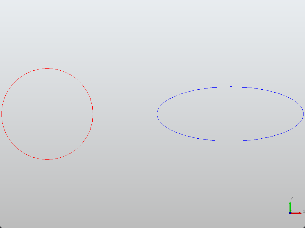
圆、椭圆
from OCC.Core.gp import gp_Pnt, gp_Ax2, gp_Dir
from OCC.Core.GC import GC_MakeCircle, GC_MakeEllipse
from OCC.Core.BRepBuilderAPI import BRepBuilderAPI_MakeEdge
from OCC.Display.SimpleGui import init_display

display, start_display, _, _ = init_display()

# 创建圆
circle_center = gp_Pnt(-10, 0, 0)
circle = GC_MakeCircle(gp_Ax2(circle_center, gp_Dir(0,0,1)), 5).Value()
circle_edge = BRepBuilderAPI_MakeEdge(circle).Edge()

# 创建椭圆
ellipse_center = gp_Pnt(10, 0, 0)
ellipse = GC_MakeEllipse(
    gp_Ax2(ellipse_center, gp_Dir(0,0,1)),
    8,  # 长轴半径
    3   # 短轴半径
).Value()
ellipse_edge = BRepBuilderAPI_MakeEdge(ellipse).Edge()

display.DisplayShape(circle_edge, color="red")
display.DisplayShape(ellipse_edge, color="blue")
display.View_Top()
display.FitAll()

start_display()
圆弧
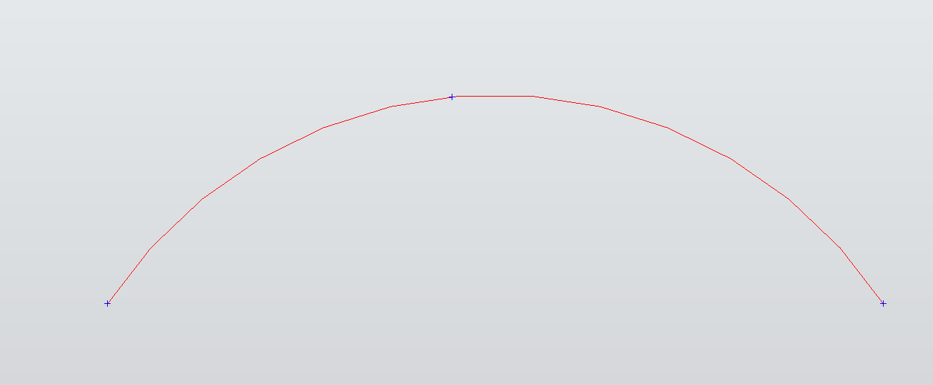
三点画弧
from OCC.Display.SimpleGui import init_display
from OCC.Core.gp import gp_Pnt
from OCC.Core.GC import GC_MakeArcOfCircle
from OCC.Core.BRepBuilderAPI import BRepBuilderAPI_MakeEdge, BRepBuilderAPI_MakeVertex

# 三点画弧
p1, p2, p3 = gp_Pnt(0,0,0), gp_Pnt(20,12,0), gp_Pnt(45,0,0)
mk = GC_MakeArcOfCircle(p1, p2, p3)

arc = mk.Value()
edge = BRepBuilderAPI_MakeEdge(arc).Edge()

v1 = BRepBuilderAPI_MakeVertex(p1).Vertex()
v2 = BRepBuilderAPI_MakeVertex(p2).Vertex()
v3 = BRepBuilderAPI_MakeVertex(p3).Vertex()

# 显示
display, start_display, *_ = init_display()
display.DisplayShape(edge, color="RED",  update=True)
display.DisplayShape(v1, color="blue", update=False)
display.DisplayShape(v2, color="blue", update=False)
display.DisplayShape(v3, color="blue", update=False)

display.FitAll()
display.View_Top()
start_display()
圆上两点画弧
from OCC.Display.SimpleGui import init_display
from OCC.Core.gp import gp_Pnt, gp_Ax2, gp_Dir, gp_Circ
from OCC.Core.GC import GC_MakeArcOfCircle
from OCC.Core.BRepBuilderAPI import BRepBuilderAPI_MakeEdge, BRepBuilderAPI_MakeVertex

# 定义圆(半径=30,圆心在原点,法向 +Z)
ax2 = gp_Ax2(gp_Pnt(0, 0, 0), gp_Dir(0, 0, 1))
circ = gp_Circ(ax2, 30)

# 两个点(必须在圆上)
p1 = gp_Pnt(30, 0, 0)   # X 轴正向
p2 = gp_Pnt(0, 30, 0)   # Y 轴正向

# 构造弧:从 p1 到 p2,sense=True 表示取圆的正向弧段
mk = GC_MakeArcOfCircle(circ, p1, p2, True)
assert mk.IsDone(), mk.Status()

arc = mk.Value()
edge = BRepBuilderAPI_MakeEdge(arc).Edge()

v1 = BRepBuilderAPI_MakeVertex(p1).Vertex()
v2 = BRepBuilderAPI_MakeVertex(p2).Vertex()

# 显示
display, start_display, *_ = init_display()

# 显示弧线
display.DisplayShape(edge, color="RED", update=False)

# 显示控制点
display.DisplayShape(v1, color="BLUE", update=False)
display.DisplayShape(v2, color="BLUE", update=False)

# 调整点的大小
display.FitAll()
display.View_Top()

start_display()
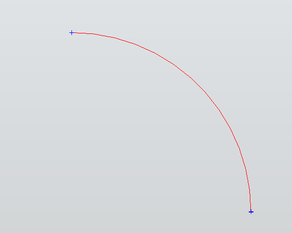
一点+扫角画弧
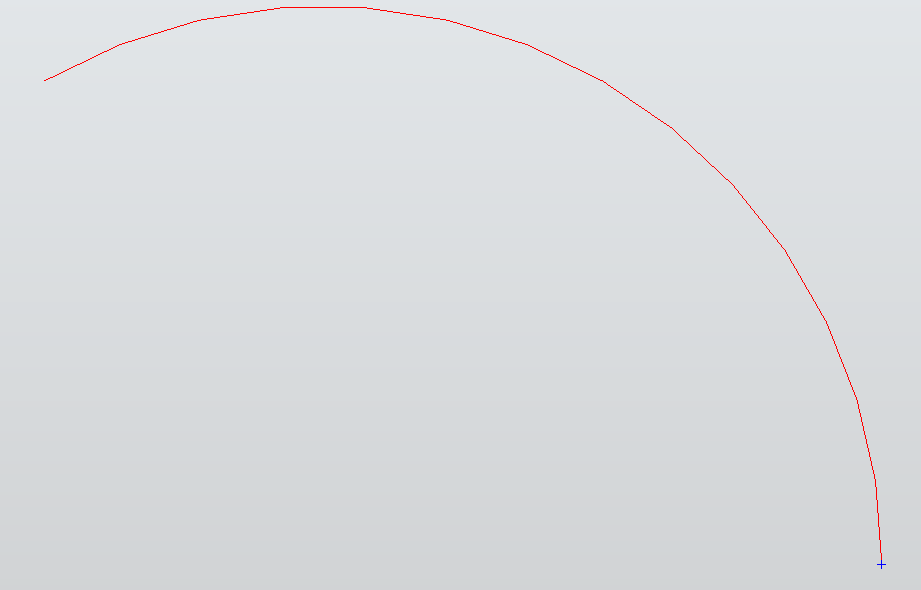
from math import radians
from OCC.Display.SimpleGui import init_display
from OCC.Core.gp import gp_Pnt, gp_Ax2, gp_Dir, gp_Circ
from OCC.Core.GC import GC_MakeArcOfCircle
from OCC.Core.BRepBuilderAPI import (
    BRepBuilderAPI_MakeEdge,
    BRepBuilderAPI_MakeVertex,
)

if __name__ == "__main__":
    # 1) 定义圆:圆心(0,0,0),法向 +Z,半径 = 30
    ax2  = gp_Ax2(gp_Pnt(0, 0, 0), gp_Dir(0, 0, 1))
    circ = gp_Circ(ax2, 30.0)

    # 2) 起点(必须在圆上):取 X 轴正向
    p0 = gp_Pnt(30.0, 0.0, 0.0)

    # 3) 扫角:正向 120°
    alpha = radians(120)
    sense = True          # True 表示沿圆的正向(右手法则)截取

    # 4) 构造弧
    mk = GC_MakeArcOfCircle(circ, p0, alpha, sense)
    arc  = mk.Value()                            # Geom_TrimmedCurve
    edge = BRepBuilderAPI_MakeEdge(arc).Edge()   # 转拓扑边用于显示/后续建模

    v_start = BRepBuilderAPI_MakeVertex(p0).Vertex()

    display, start_display, *_ = init_display()
    display.DisplayShape(edge, color="RED", update=False)
    display.DisplayShape(v_start, color="BLUE", update=False)

    display.FitAll()
    display.View_Top()
    start_display()
插值样条曲线
类似于Abaqus草图中的Create Spline。
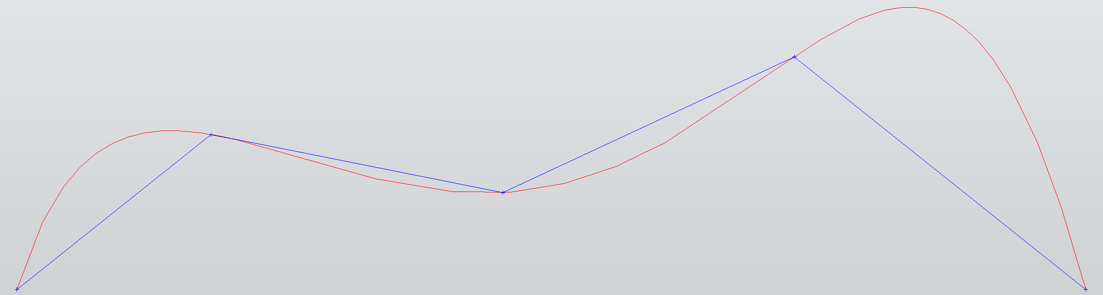
from OCC.Display.SimpleGui import init_display
from OCC.Core.gp import gp_Pnt
from OCC.Core.GeomAPI import GeomAPI_PointsToBSpline
from OCC.Core.TColgp import TColgp_Array1OfPnt
from OCC.Core.BRepBuilderAPI import (
    BRepBuilderAPI_MakeEdge,
    BRepBuilderAPI_MakeVertex,
)

# 插值点(曲线将通过这些点)
pts = [
    gp_Pnt(0, 0, 0),
    gp_Pnt(10, 8, 0),
    gp_Pnt(25, 5, 0),
    gp_Pnt(40, 12, 0),
    gp_Pnt(55, 0, 0),
]

# 1-based 数组填充(OCCT 的 Array1 是从 1 开始)
arr = TColgp_Array1OfPnt(1, len(pts))
for i, p in enumerate(pts, start=1):
    arr.SetValue(i, p)

# 构造 B 样条(插值)
mk = GeomAPI_PointsToBSpline(arr)
bspline = mk.Curve()

# 转成 Edge 以显示/参与建模
edge = BRepBuilderAPI_MakeEdge(bspline).Edge()

# 显示
display, start_display, *_ = init_display()
display.DisplayShape(edge, color="RED", update=False)

# --- 绘制控制点 ---
for p in pts:
    v = BRepBuilderAPI_MakeVertex(p).Vertex()
    display.DisplayShape(v, color="BLUE", update=False)

# ---绘制控制多边形 ---
for a, b in zip(pts[:-1], pts[1:]):
    e = BRepBuilderAPI_MakeEdge(a, b).Edge()
    display.DisplayShape(e, color="BLUE", update=False)

display.FitAll()
display.View_Top()
start_display()
内置方法
gp_Pnt
用于存储和操作三维坐标点
gp_Dir
三维空间中的单位方向向量,主要用于定义方向、法线或旋转轴等几何属性
gp_Vec
普通向量,可任意长度
gp_Ax1
一条有方向的几何轴
gp_Ax1(P (gp_Pnt), V (gp_Dir))
gp_Ax2
三维坐标系(原点 + 三个正交方向)
默认构造(世界坐标系)
原点+Z轴+X参考
gp_Ax2(P, N, Vx)
origin_P (gp_Pnt):坐标系的原点位置,例如 gp_Pnt(1,2,3)Z_direction_N (gp_Dir):指定坐标系的Z轴正方向(必须为单位向量)X_reference_Vx (gp_Dir):用于确定X方向的参考向量(不必与Z轴垂直)
坐标系的X轴通过叉积计算:\(X = (N × Vx) × N\),将 Vx投影到与Z轴垂直的平面上;坐标系的Y轴通过右手定则确定,\(Y = Z × X\)。
通过原点+主方向自动构造
gp_Ax2(P, V)
当只提供主方向时,系统按以下规则自动补全坐标系:
- Z轴:直接使用输入的 main_direction_V
- 自动选择一个与 V 不平行的方向作为 X 轴,然后通过右手法则确定 Y 轴